


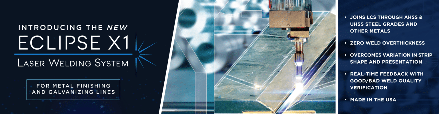
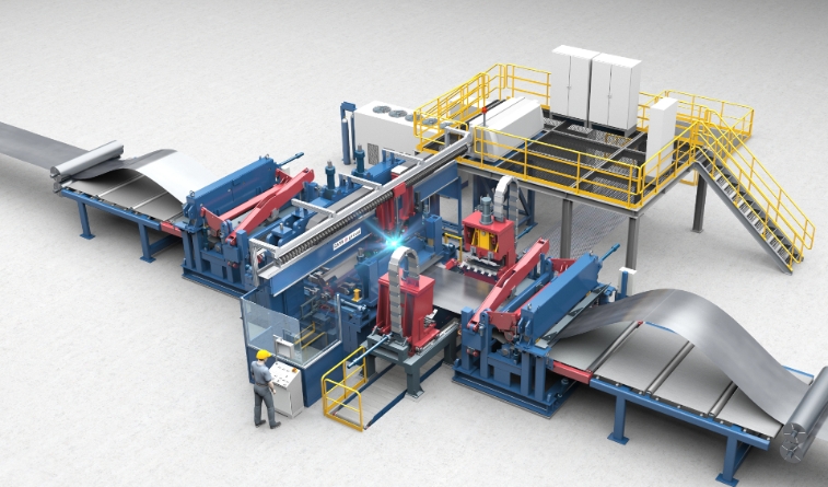
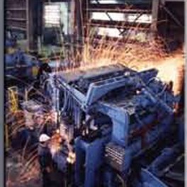
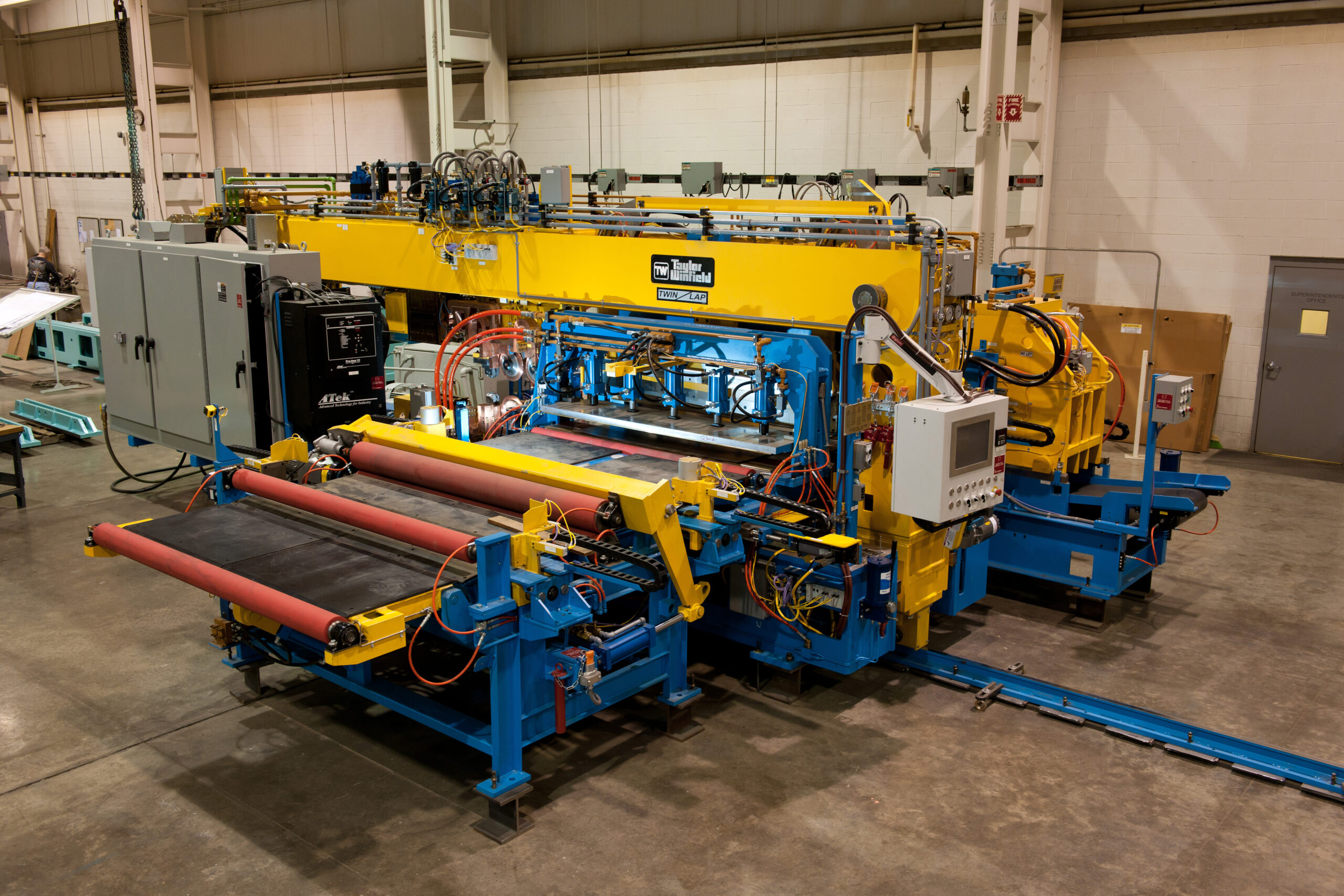
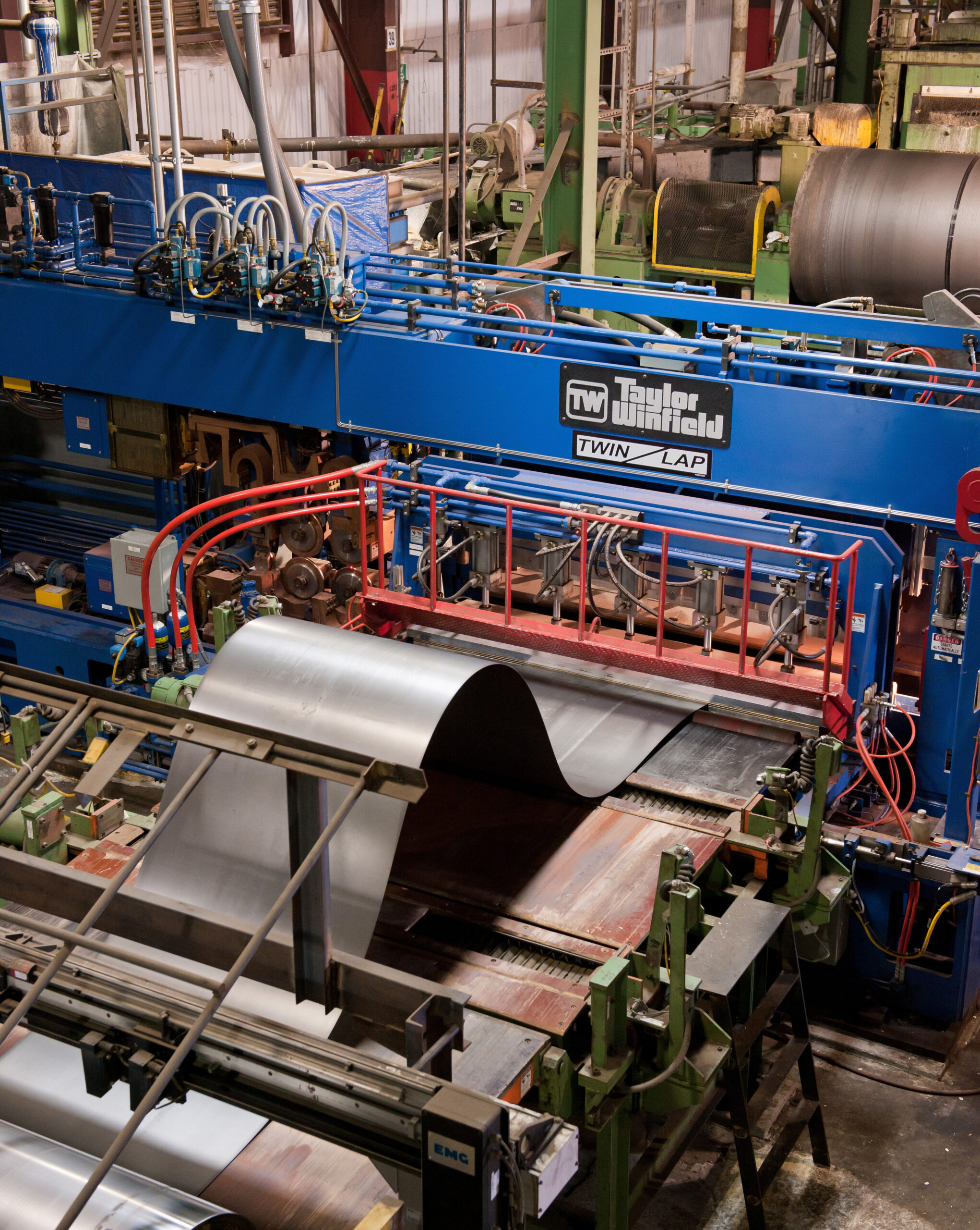
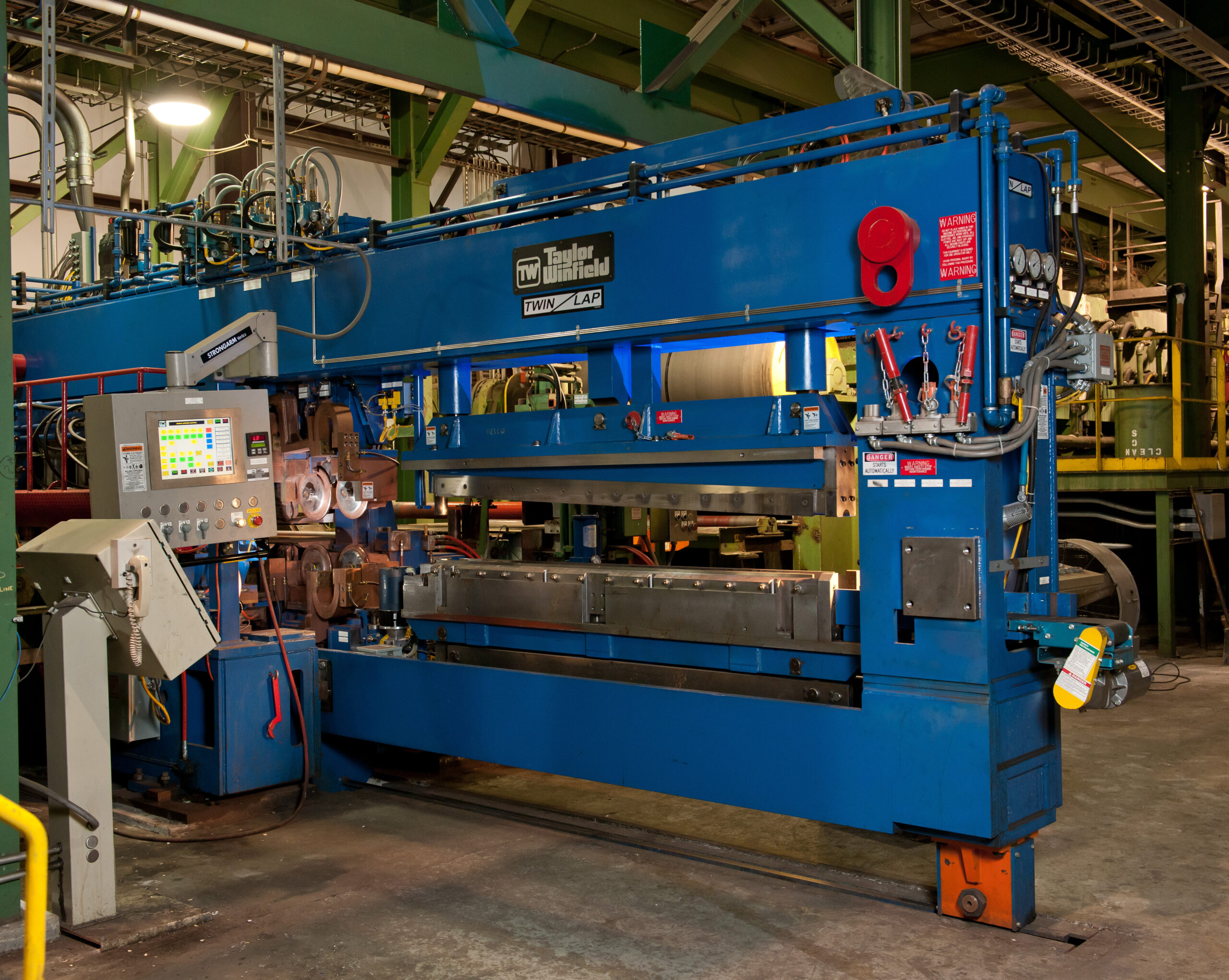
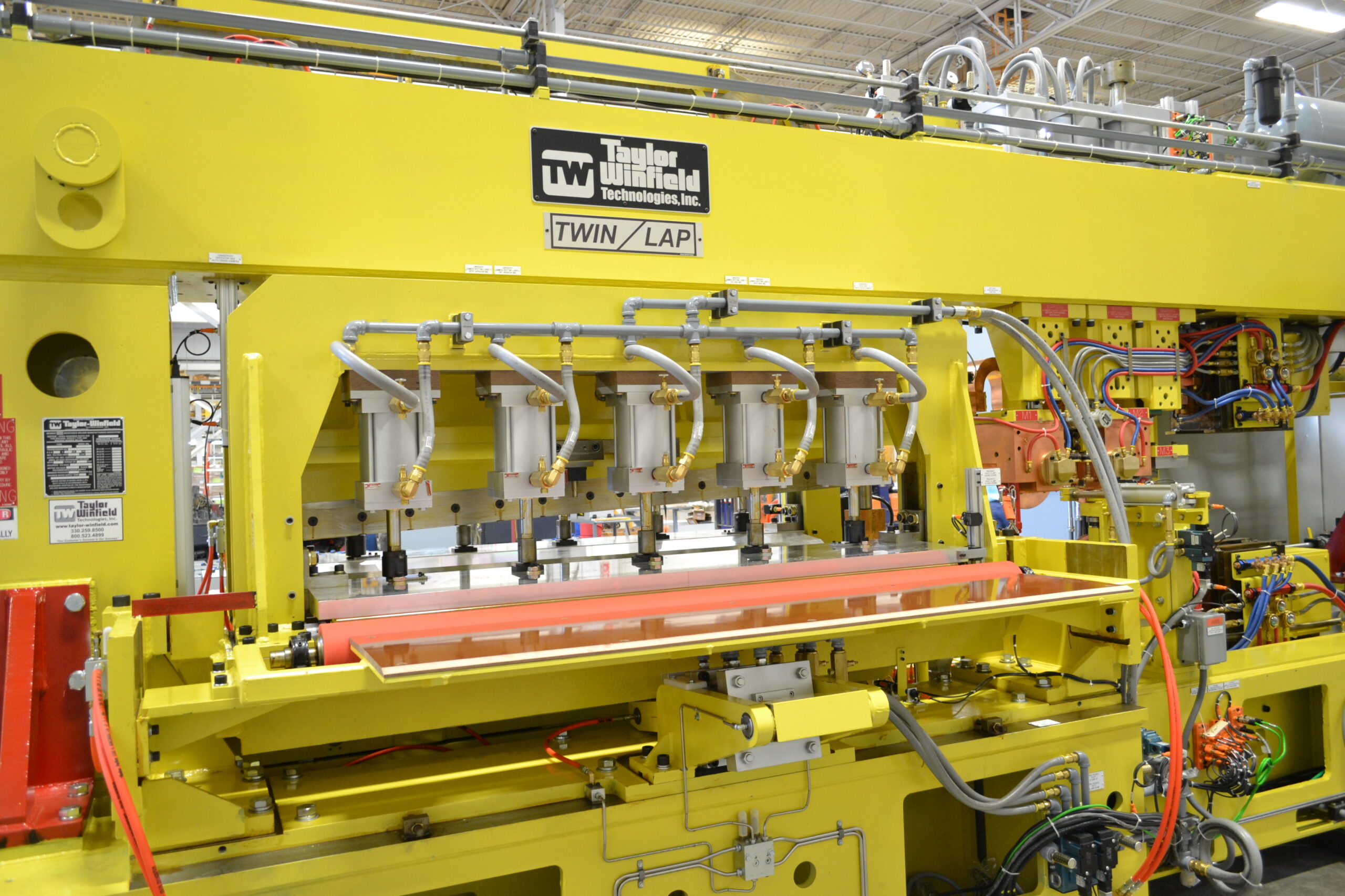
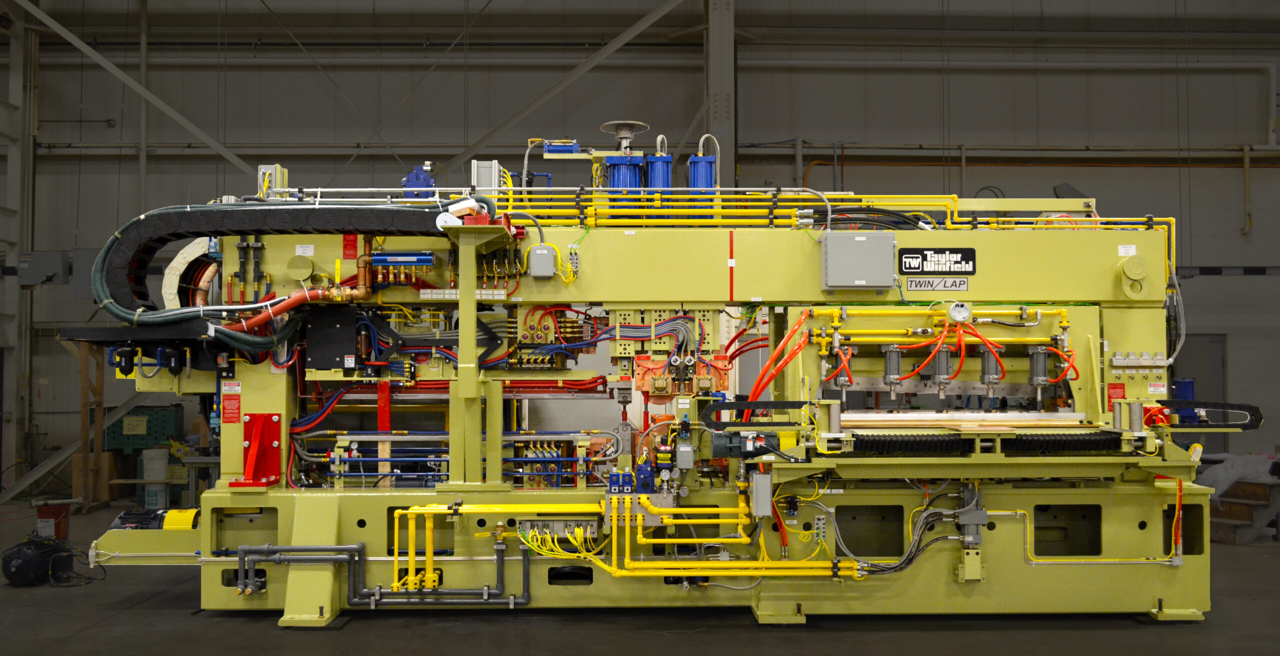
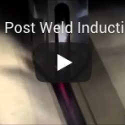
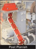
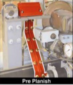
 Flash-Butt Welding is an ultra-fast joining process with fusion occurring over the entire weld area simultaneously. It is the only resistance welding technique in which surface scale has little or no effect on the weld quality and consistency — a major reason for its use in pickling lines. After trimming, flash-butt welds are as thin as the strip itself and pass readily through subsequent reduction and forming equipment. In most cases, the welds lose their identity and continue on into the consumer product. Flash-Butt Welders predominate in pickle lines, but are also used in heavy-gauge Coil Preparation, Shot Blasting, Side Trimming and Slitting Lines, and Welded Tube and Pipe Mills. Combination Flash-Butt Welders, appropriately named because they have a built-in, draw-cut weld trimmer which, in one stroke, removes the excess metal extruded to the surfaces of the strip during the upsetting (forging) portion of the welding cycle. A transfer mechanism successively moves the joint to the trimming station and other optional work stations, which include an edge punching or notching station and/or induction post-heating system. The latter minimizes costly strip breakage by tempering the heat-affected zone in alloy steels susceptible to treatment.
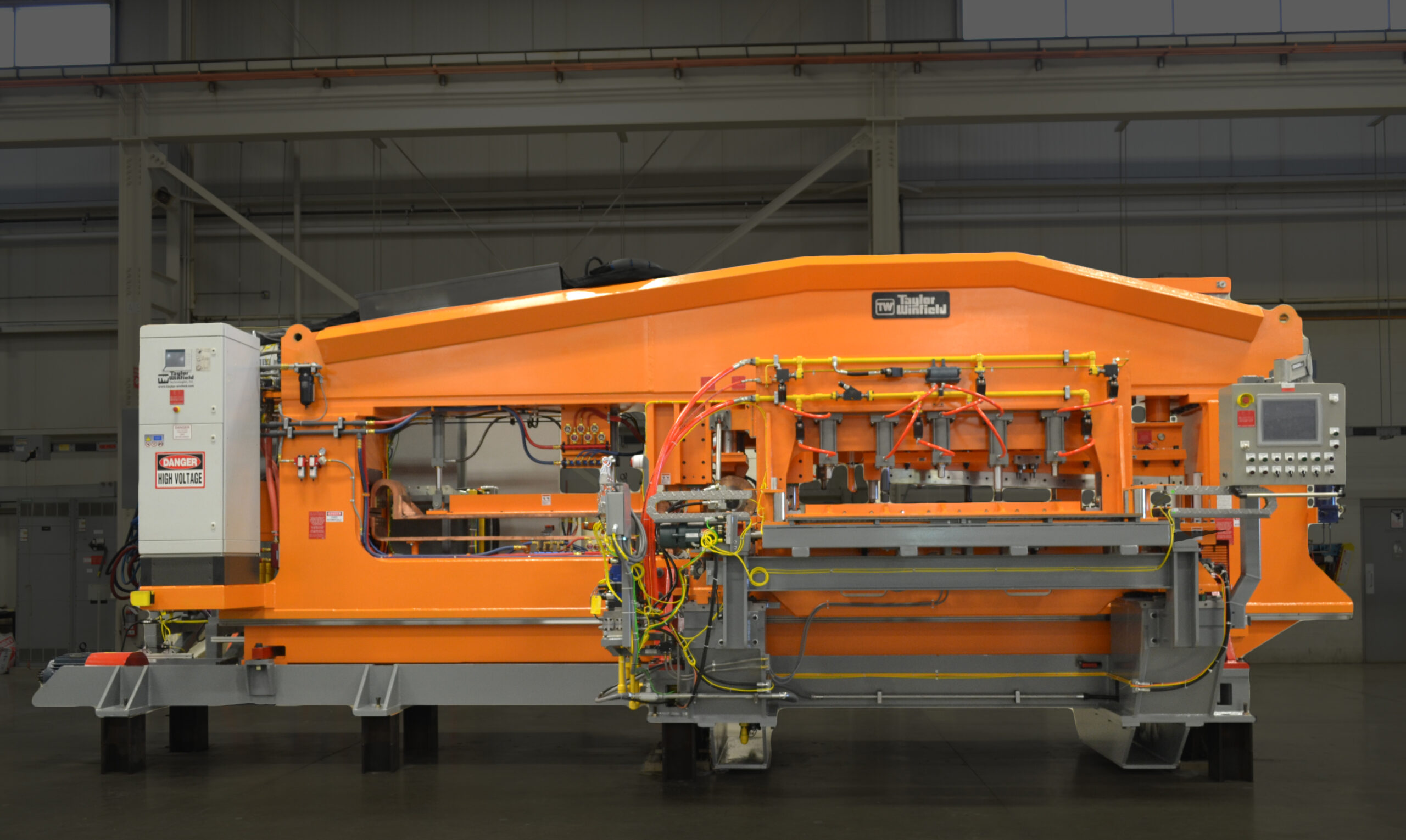
WHY OUR CUSTOMERS PARTNER WITH
TAYLOR-WINFIELD TECHNOLOGIES
As a Capital Equipment Manufacturer, we provide standard & custom engineered parts production solutions, all under one roof. From concept through engineering, assembly and test, we have the expertise, resources, and commitment to ensure quality equipment & total “life” support for all the equipment we manufacture.